This step-by-step guide is for MRI students, radiographers, and technologists who wish to improve their planning skills and master the thoracic spine MRI protocol.
What you will learn:
Key factors in thoracic spine MRIs, including trade-offs.
Patient and scanner setup tips.
Best pulse sequences and planning techniques.
Ways to avoid common artifacts.
What great thoracic spine images should look like.
Key Takeaways
Prioritize scan time, then SNR, then resolution.
The thoracic spine is heavily affected by breathing and cardiac motion, making motion artifacts the biggest problem. We're also imaging near air-filled lungs with low proton density, creating challenging conditions for signal quality. This makes SNR our second priority. Resolution comes third, though we still need good detail to see ligaments, disc herniations, and spinal cord structures.
We mainly use Turbo Spin Echo sequences in thoracic spine MRIs.
These sequences provide fast acquisition with excellent soft tissue contrast. They work well for T2, T1, and STIR weightings, helping us assess the thoracic spine and detect common pathologies while keeping scan time short.
Avoid these 5 common thoracic spine artifacts.
Artifacts
Solution – How to Avoid It
Motion artifacts
Place a saturation band anterior to the spine on all sagittal sequences to suppress motion from cardiac pulsation, respiration, and aortic flow.
Susceptibility artifacts
Use spin echo sequences instead of gradient echo to reduce sensitivity to magnetic field inhomogeneities near air-tissue interfaces.
Flow and motion artifacts
Ghosts follow the phase axis. Use foot-head on sagittal and coronal. On axials, pick AP or RL, so ghosting misses the canal.
Chemical shift artifacts
Increase the bandwidth to reduce spatial displacement between fat and water signals.
Wrap-around artifacts
Activate foldover suppression when anatomy extends past the FOV along the phase direction.
Intro to Thoracic Spine MRIs
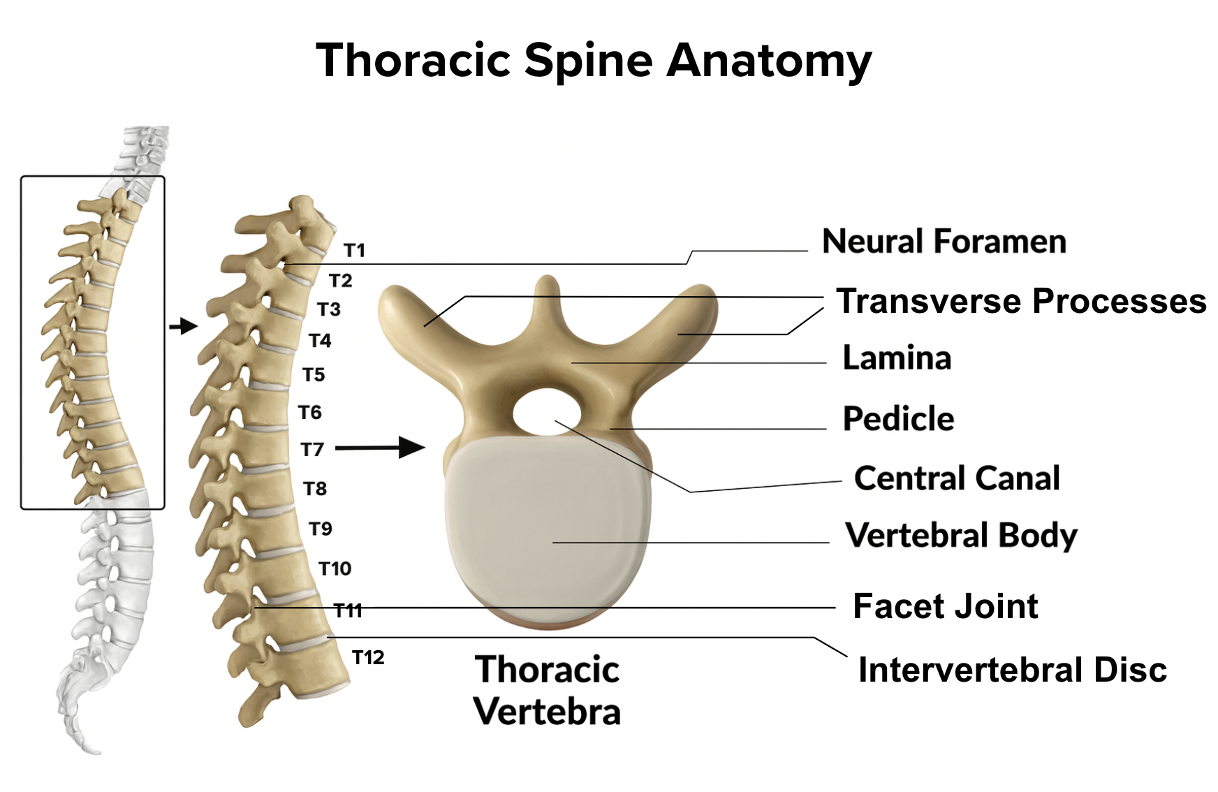
The thoracic spine is the mid-back region that bridges the cervical and lumbar spine. It consists of 12 thoracic vertebrae (T1–T12) and serves as the structural foundation for the rib cage. This region protects vital organs, supports the upper body, and houses the spinal cord and nerve roots.
Because of its proximity to the heart and lungs, the thoracic spine is particularly susceptible to motion artifacts from breathing and cardiac pulsation. It's also a common source of pain, neurological symptoms, and pathologies affecting the spinal cord and surrounding structures.
How to Balance the 3 Trade-offs in Thoracic Spine MRIs
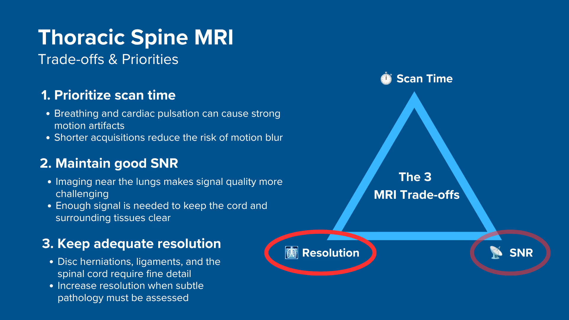
In MRI, we always face a trade-off between 3 key metrics:
Scan Time: How fast a pulse sequence can be completed.
Resolution: How much detail the image can display.
SNR: How clear the image is, how much signal relative to noise.
Improving one of these metrics reduces the performance of the others. To decide what trade-offs to make, we must consider the needs of each clinical situation.
For thoracic spine MRIs, we face these challenges:
The thoracic spine is heavily affected by motion from breathing and cardiac pulsation, making motion artifacts the number one image quality problem. Long scan times increase the opportunity for motion blur, which can make images completely unreadable.
The thoracic region has inherently challenging conditions for signal quality because we're imaging near the lungs, which are air-filled with low proton density. This creates strong air-tissue interfaces and high susceptibility.
The thoracic spine has many fine structures like small ligaments, disc herniations, and the spinal cord itself.
Therefore, we typically:
Prioritize scan time to avoid motion artifacts,
Keep SNR good to ensure enough image clarity, and
Optimize for resolution when finer details must be assessed.
Short scan times reduce the risk of motion blur from breathing and cardiac pulsation. Strong SNR helps us distinguish between the spinal cord, cerebrospinal fluid, and surrounding tissues clearly. We need good resolution to see fine structures, but we can't push it so high that it destroys our scan time or SNR.
Note! Prioritizing scan time in thoracic spine MRIs is only a general guideline, NOT a strict rule. If motion is well-controlled or if you need to visualize very fine details, your priorities may shift. The right balance always depends on the needs of your patient and clinic.
Thoracic Spine Health Conditions and the MRI Sequences That Reveal Them
The thoracic spine MRI study can help us diagnose a wide range of health conditions. The table below lists some of the most common conditions and the pulse sequences that reveal them:
Highlights water-rich tissues like CSF, soft tissue, and inflamed discs, which appear bright due to their high water content. Herniated discs appear as bulges or extrusions that may compress the spinal cord or nerve roots. Bright CSF outlines the cord, so canal narrowing and compression are directly visible.
Structural and Neoplastic Changes:
• Spinal fractures
• Spinal tumors
• Bone marrow changes
T1 TSE
Best view of vertebral bodies, epidural fat, and marrow. Marrow changes vary in direction, so read with T2 and STIR.
Inflammatory and Infectious Conditions:
• MS plaques
• Discitis and osteomyelitis
• Abscesses
• Bone marrow edema
STIR TSE
Suppresses fat signals completely, making water-rich tissues stand out even clearer than on T2. This makes STIR ideal for detecting subtle edema, inflammation, and infections, where increased water content would otherwise be obscured by fat. Provides high lesion visibility for inflammatory conditions.
How to Perform a Thoracic Spine MRI
The step-by-step guide below will show you how to set up and perform a thoracic spine MRI protocol in practice.
We will perform the protocol in 3 parts:
Set up the Patient and MRI Scanner
Plan and Acquire the Protocol Sequences
Review the Images
Part 1: Set up the Patient and MRI Scanner
1. Position the Patient in the Scanner
Lay the patient supine with the mid-thoracic region at the scanner's isocenter, using the orientation your department specifies. Head-first supine is the common default, though feet-first is used on some systems.
Centering the mid-thoracic region at isocenter keeps the anatomy in the most homogeneous part of the field.
Place a dedicated thoracic spine coil at the patient's back. This coil ensures you get full coverage of the thoracic region and delivers strong signal acquisition for clear images. The coil should be positioned to cover all 12 thoracic vertebrae.
Once the patient is in place, review your scanner's hardware settings.
In this guide, we will use the following settings:
Scanner Setting
Value
Why This Value
Magnetic field strength
1.5 T
The most common clinical field strength, giving enough SNR for this protocol with less susceptibility and B1 artifact than 3 T.
Maximum gradient strength
45 mT/m
Provides strong, versatile gradient performance that supports fast imaging and precise spatial encoding.
This hardware setup is widely used in clinical practice. It balances acquisition time, image quality, and patient comfort.
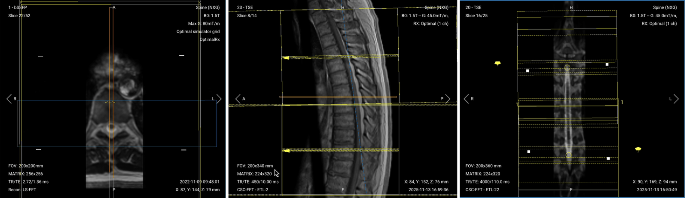
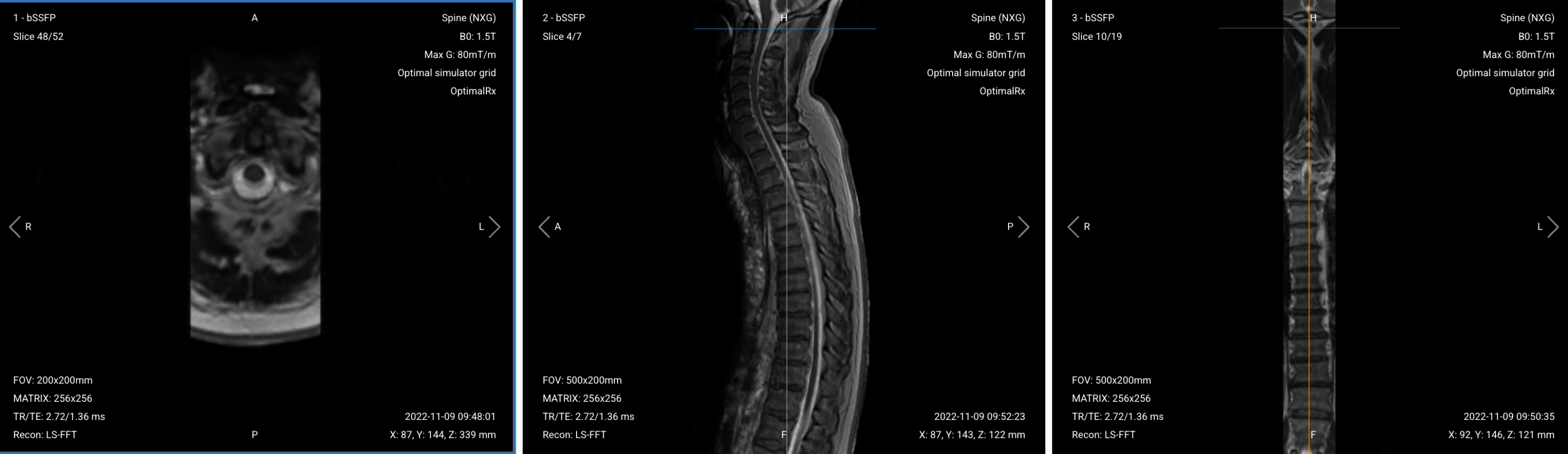
3. Capture the Initial Localizer Images
Before we can perform any MRI protocol, we must always capture initial localizer images of the patient. These images act as a guide for planning the detailed scans we will perform next.
We should always capture localizers in three planes:
Axial
Sagittal
Coronal
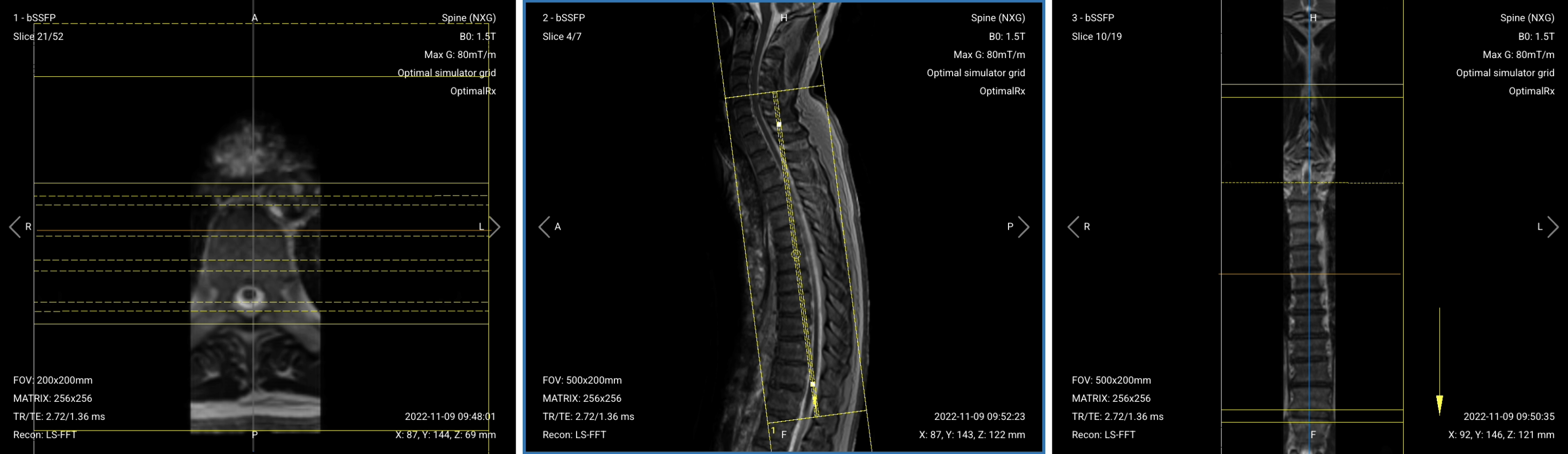
Once acquired, load the initial localizer images into the three viewports.
Then, scroll through each of the image stacks to locate a central slice that clearly shows the anatomy of the thoracic spine.
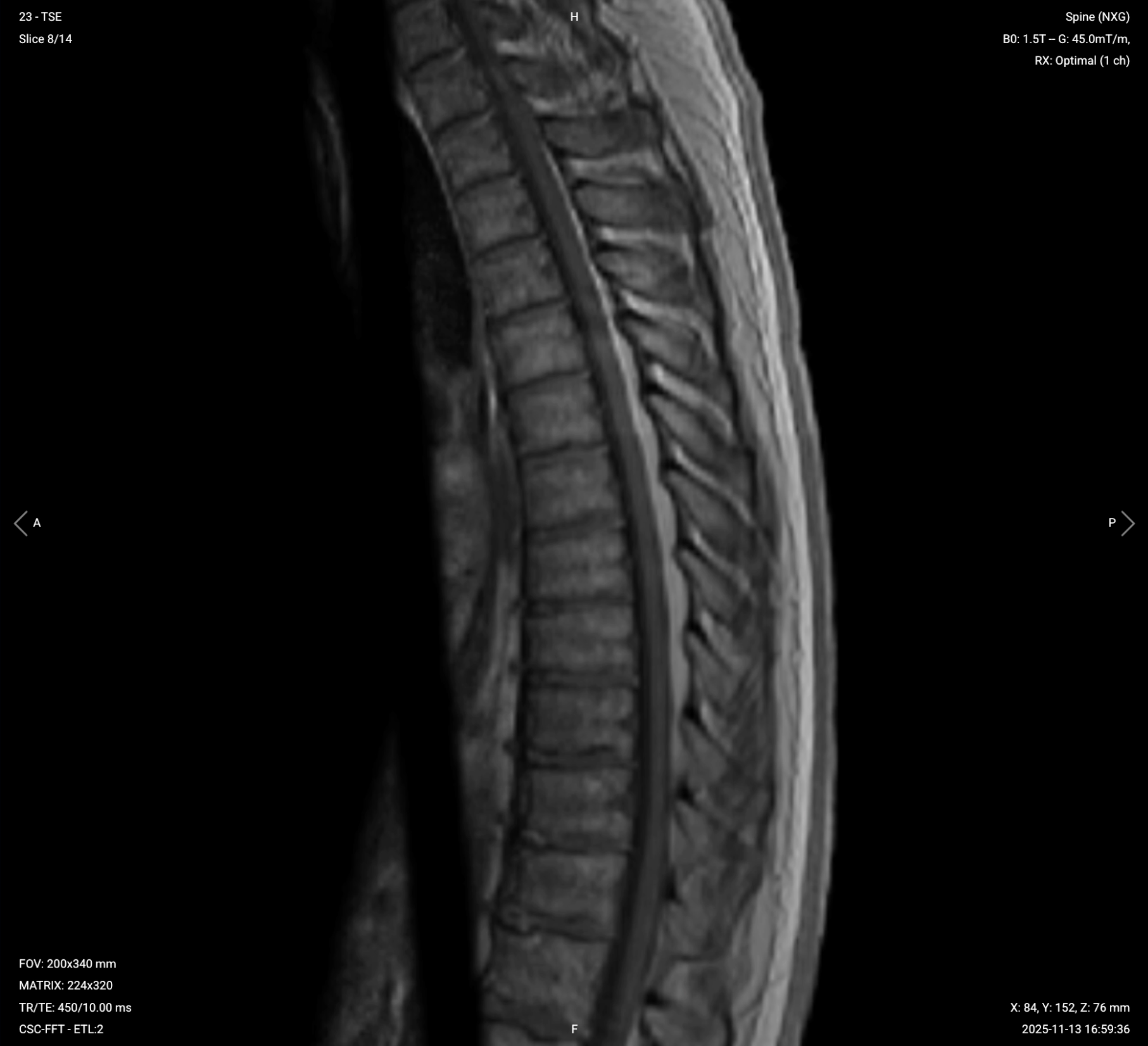
✅ Correct Setup of Localizer Images for Thoracic Spine MRI:
Part 2: Plan and Acquire the Protocol Sequences
When all preparations are ready, we can start planning and acquiring the protocol sequences.
Let's go through the pulse sequences a standard thoracic spine MRI protocol includes, why we perform them, and how to set them up.
The 5 Planning Steps of a Standard Thoracic Spine MRI Protocol
Coronal T2 TSE
Sagittal T2 TSE
Sagittal STIR TSE
Sagittal T1 TSE
Axial T2 and T1 TSE (Single or Double Stack)
The axial T2 and T1 are planned together but acquired separately, so a full protocol is six acquisitions.
We mainly use Turbo/Fast Spin Echo sequences for this study. These sequences provide fast acquisition with excellent soft tissue contrast. They work well for creating multiple contrasts, including T2, T1, and inversion recovery for fat suppression. This helps us assess the thoracic spine and detect common pathologies while keeping scan time short.
In the sections below, we go through how to plan and set up each sequence.
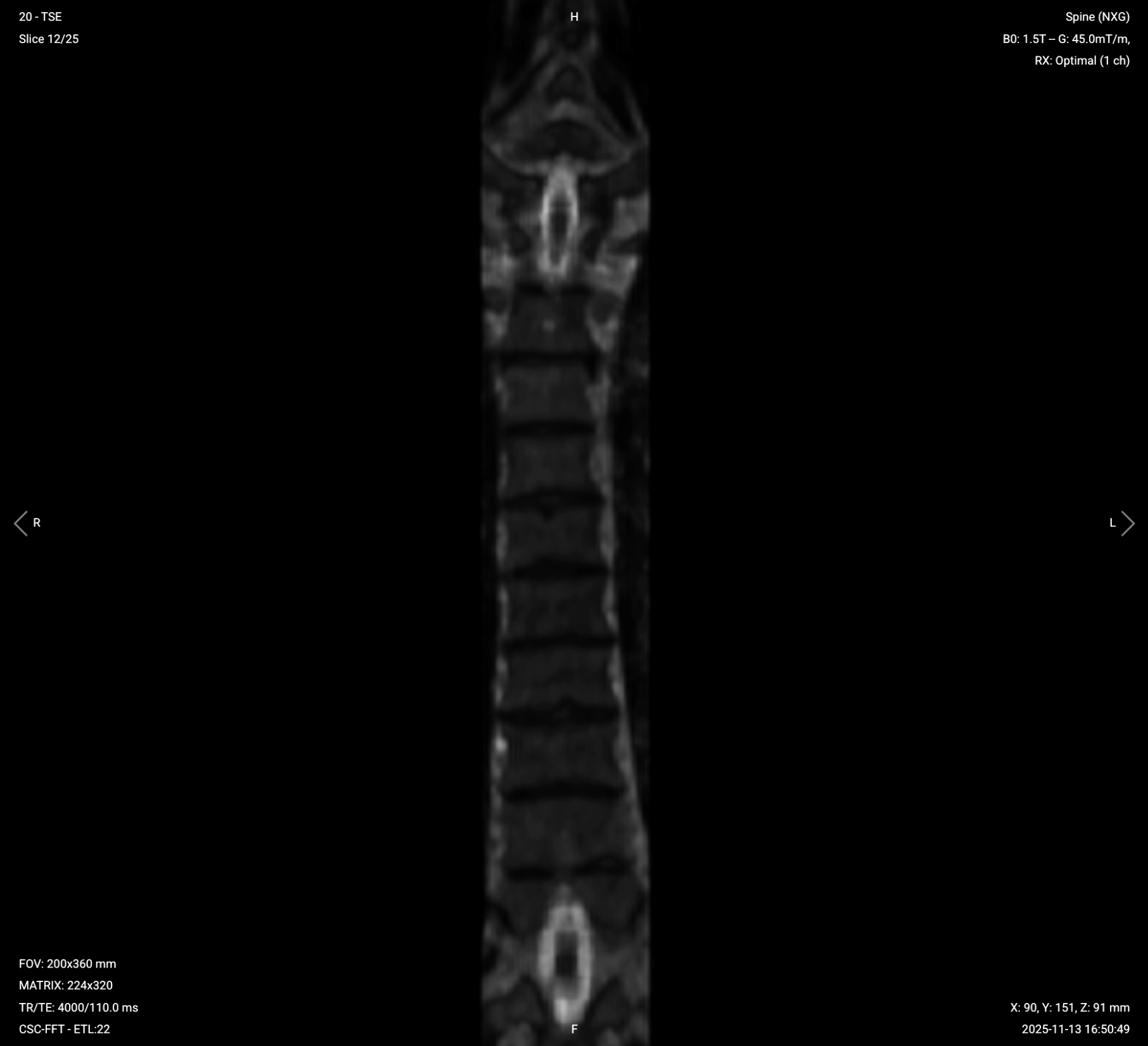
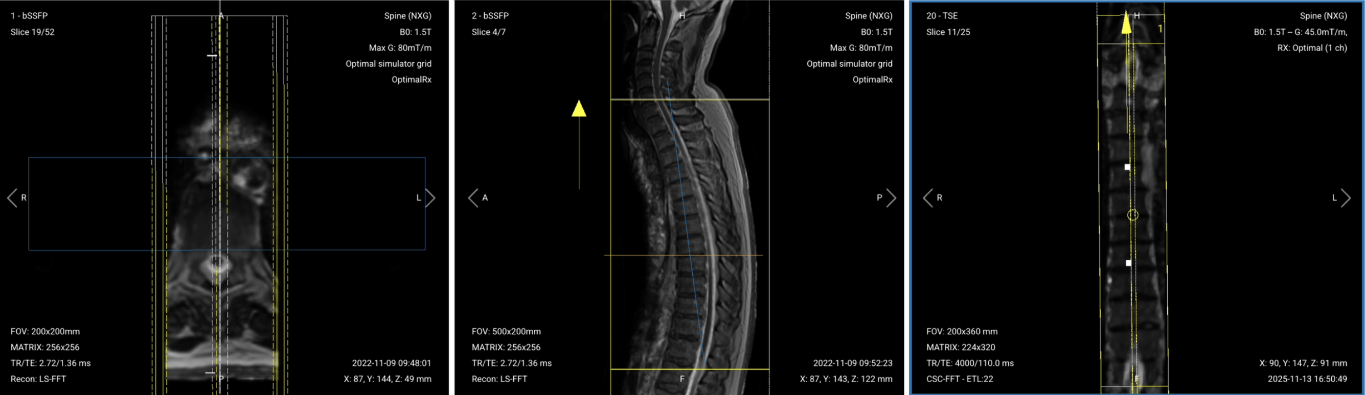
1. Planning Coronal T2 TSE
✅ Correct Planning:
Planning Instructions:
Use the spinal cord and transverse processes as your anatomical references.
Align the slices as follows:
Axial Localizer: Parallel to the transverse processes of the thoracic vertebrae.
Sagittal Localizer: Follow the natural arch of the spinal cord through the thoracic region.
Use appropriate geometry parameters:
Slice number: Enough to cover the vertebral bodies back through the transverse processes, typically 22–26 slices.
Slice thickness: 4 mm, thick enough for good SNR while maintaining adequate resolution.
Slice gap: 0.4 mm, 10% of slice thickness to prevent crosstalk while ensuring continuity.
Set the foldover direction (phase encoding) to foot-head (FH). Foldover suppression is then needed, since the head and pelvis fall outside the field of view along this axis.
Ensure the field of view covers the transverse processes bilaterally without cutting them off.
Include at least one cervical vertebra above T1 and one lumbar vertebra below T12 for complete coverage.
Parameters for Coronal T2 TSE:
Parameter
Recommended Values
Why These Values
Echo Time (TE)
100–120 ms
Long TE is required for T2 contrast.
Repetition Time (TR)
4,000–6,000 ms
Long TR is required for T2 contrast.
Field-of-View (FOV)
200 × 360 mm
Covers the full superior-to-inferior extent. Scan time follows the foot-head phase steps, not the left-right width.
Matrix
224 × 320
Medium matrix size to get sufficient resolution and detail while maintaining short scan time and high SNR.
Foldover Direction (Phase)
Foot-to-Head (FH)
Keeps fine left-right detail in the frequency direction and sends CSF ghosting along the cord. Needs foldover suppression.
Number of Slices
22–26
Covers the vertebral bodies back to the transverse processes. Superior-to-inferior coverage comes from the FOV.
Slice Thickness
4 mm
Thick enough to keep SNR up across the full thoracic coverage, while still resolving the transverse processes.
Slice Gap
0.4 mm
10% of slice thickness, which limits cross-talk without hiding anatomy.
NEX / Averages
1–2
To get enough SNR, while keeping scan time short.
Turbo Factor / ETL
16–24
Higher turbo factor reduces scan time, and long effective TE provides T2 weighting.
Bandwidth per pixel
200–250 Hz/px
Roughly matches the 220 Hz fat-water shift at 1.5 T, holding displacement near one pixel without giving up SNR.
Foldover Suppression
Yes
To avoid aliasing or wrap-around artifacts.
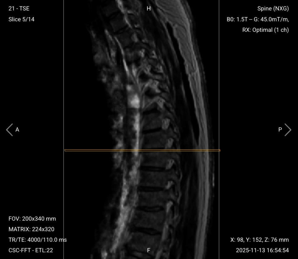
2. Planning Sagittal T2 TSE
✅ Correct Planning:
Planning Instructions:
Use the spinal cord as your anatomical reference.
Align the slices as follows:
Axial Localizer: Center the slices over the vertebral bodies.
Coronal Localizer: Parallel to the spinal cord, following the natural curvature of the thoracic spine.
Use appropriate geometry parameters:
Slice number: Enough to cover the thoracic spine from right to left, including surrounding muscles and tendons, typically 14–18 slices.
Slice thickness: 4 mm, thick enough for good SNR while maintaining adequate resolution.
Slice gap: 0.4 mm, 10% of slice thickness to prevent crosstalk while ensuring continuity.
Set the foldover direction (phase encoding) to foot-head (FH). Ghosts follow the phase axis, so this sends CSF pulsation ghosting along the cord rather than across it.
Ensure coverage extends from at least one cervical vertebra to one lumbar vertebra.
Position slices to cover the paraspinal muscles and tendons, but not past the edge of the collimated localizer coverage.
Use saturation bands placed anterior to the thoracic spine to suppress motion artifacts. Place the band over the heart, lungs, and aorta inside the field of view, close to the spine but stopping short of it, so the moving tissue is saturated and the spine is not. Saturation bands add RF pulses and raise patient heating, so watch the SAR indicator when using them across several sequences, and leave the band off where motion is already controlled.
Parameters for Sagittal T2 TSE:
Parameter
Recommended Values
Why These Values
Echo Time (TE)
100–120 ms
Long TE is required for T2 contrast.
Repetition Time (TR)
4,000–6,000 ms
Long TR is required for T2 contrast.
Field-of-View (FOV)
200 × 340 mm
Covers the full superior-to-inferior extent. Scan time follows the foot-head phase steps, not the anterior-posterior depth.
Matrix
224 × 320
Medium matrix size provides sufficient resolution while maintaining short scan time and high SNR.
Foldover Direction (Phase)
Foot-to-Head (FH)
Ghosts follow the phase axis, so CSF pulsation ghosting runs along the cord rather than across it.
Number of Slices
14–18
Enough slices to cover the thoracic spine from right to left.
Slice Thickness
4 mm
Thick enough to keep SNR up across the full thoracic coverage, while still resolving the cord and disc margins.
Slice Gap
0.4 mm
10% of slice thickness, which limits cross-talk without hiding anatomy.
NEX / Averages
1–2
To get enough SNR, while keeping scan time short.
Turbo Factor / ETL
16–24
Higher turbo factor reduces scan time, and long effective TE provides T2 weighting.
Bandwidth per pixel
200–250 Hz/px
Roughly matches the 220 Hz fat-water shift at 1.5 T, holding displacement near one pixel without giving up SNR.
Foldover Suppression
Yes
Prevents aliasing or wrap-around artifacts.
Saturation Bands
Yes
Placed anterior to the spine to suppress cardiac, respiratory, and vascular motion artifacts.
3. Planning Sagittal STIR TSE
✅ Correct Planning:
Planning Instructions:
Copy the slice geometry and planning from the previous sagittal T2 TSE sequence.
Keep the same slice angulation, coverage, and positioning to ensure images of different contrasts can be clearly compared.
Use saturation bands placed anterior to the thoracic spine to suppress motion artifacts. Place the band over the heart, lungs, and aorta inside the field of view, close to the spine but stopping short of it, so the moving tissue is saturated and the spine is not.
Parameters for Sagittal STIR TSE:
Parameter
Recommended Values
Why These Values
Echo Time (TE)
20–40 ms
Medium TE balances T2 weighting with inversion recovery effects.
Repetition Time (TR)
3,000–5,000 ms
Long TR allows adequate T2 weighting while accommodating the inversion pulse.
Inversion Time (TI)
130–150 ms
Matches fat's null point at 1.5 T, where fat's T1 is short. Exact value is vendor-dependent.
Field-of-View (FOV)
200 × 340 mm
Covers the full superior-to-inferior extent. Scan time follows the foot-head phase steps, not the anterior-posterior depth.
Matrix
224 × 320
Medium matrix size provides sufficient resolution while maintaining short scan time and high SNR.
Foldover Direction (Phase)
Foot-to-Head (FH)
Ghosts follow the phase axis, so CSF pulsation ghosting runs along the cord rather than across it.
Number of Slices
14–18
Covers the thoracic spine from right to left adequately.
Slice Thickness
4 mm
Thick enough to keep SNR up across the full thoracic coverage, while still resolving the cord and disc margins.
Slice Gap
0.4 mm
10% of slice thickness, which limits cross-talk without hiding anatomy.
NEX / Averages
1–2
To get enough SNR, while keeping scan time short.
Turbo Factor / ETL
10–14
A shorter train than T2 limits blurring. Contrast also depends on echo spacing and k-space order.
Bandwidth per pixel
200–250 Hz/px
Roughly matches the 220 Hz fat-water shift at 1.5 T, holding displacement near one pixel without giving up SNR.
Foldover Suppression
Yes
Prevents wrap-around artifacts from surrounding thoracic structures.
Saturation Bands
Yes
Placed anterior to the spine to suppress cardiac, respiratory, and vascular motion artifacts.
4. Planning Sagittal T1 TSE
✅ Correct Planning:
Planning Instructions:
Copy the slice geometry and planning from the previous sagittal T2 TSE sequence.
Keep the same slice angulation, coverage, and positioning to ensure images of different contrasts can be clearly compared.
Use saturation bands placed anterior to the thoracic spine to suppress motion artifacts. Place the band over the heart, lungs, and aorta inside the field of view, close to the spine but stopping short of it, so the moving tissue is saturated and the spine is not.
Parameters for Sagittal T1 TSE:
Parameter
Recommended Values
Why These Values
Echo Time (TE)
10–20 ms
Short TE is required for T1 contrast.
Repetition Time (TR)
400–600 ms
Short TR is required for T1 contrast.
Field-of-View (FOV)
200 × 340 mm
Covers the full superior-to-inferior extent. Scan time follows the foot-head phase steps, not the anterior-posterior depth.
Matrix
224 × 320
Medium matrix size provides sufficient resolution while maintaining short scan time and high SNR.
Foldover Direction (Phase)
Foot-to-Head (FH)
Ghosts follow the phase axis, so CSF pulsation ghosting runs along the cord rather than across it.
Number of Slices
14–18
Covers the thoracic spine from right to left adequately.
Slice Thickness
4 mm
Thick enough to keep SNR up across the full thoracic coverage, while still resolving the cord and disc margins.
Slice Gap
0.4 mm
10% of slice thickness, which limits cross-talk without hiding anatomy.
NEX / Averages
1–2
To get enough SNR, while keeping scan time short.
Turbo Factor / ETL
2–3
Kept short so the effective TE stays short, preserving T1 weighting.
Bandwidth per pixel
200–250 Hz/px
Roughly matches the 220 Hz fat-water shift at 1.5 T, holding displacement near one pixel without giving up SNR.
Foldover Suppression
Yes
Prevents wrap-around artifacts.
Saturation Bands
Yes
Placed anterior to the spine to suppress cardiac, respiratory, and vascular motion artifacts.
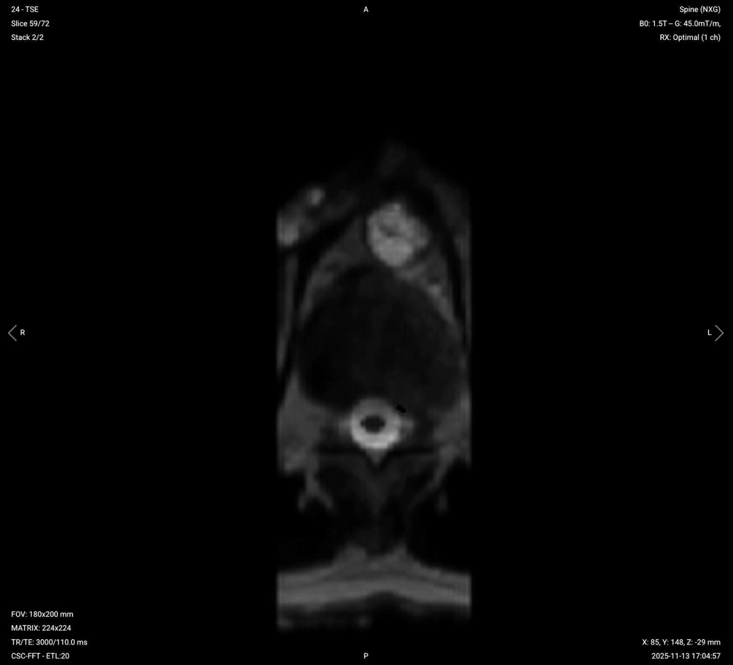
5. Planning Axial T2 and T1 TSE
✅ Correct Planning:
Planning Instructions:
Use the spinal cord and intervertebral discs as your anatomical references.
Align the slices as follows:
Coronal Localizer: Perpendicular to the spinal cord.
Sagittal Localizer: Parallel to the intervertebral disc spaces in the middle of the thoracic region.
Use appropriate geometry parameters:
Slice number: 65–75 slices, enough to cover all 12 thoracic vertebrae plus one above and below.
Slice thickness: 4 mm, thick enough for good SNR while maintaining adequate resolution.
Slice gap: 0.4 mm, 10% of slice thickness to prevent crosstalk while ensuring continuity.
Set the phase direction by where the ghosting should land. Ghosts follow the phase axis, so AP sends cardiac and respiratory ghosting across the spinal canal, and RL sends it side to side. Swap to RL, or add an anterior saturation band, if ghosting crosses the cord.
For double stack acquisitions:
Position the first stack to cover the upper thoracic region.
Position the second stack to cover the lower thoracic region.
Minimize overlap between stacks to reduce crosstalk artifacts, or position them with a small gap in an area of less clinical interest.
The angulation compared to the discs is much less than in the lumbar spine. You can use almost pure axial slices.
Parameters for Axial T2 TSE:
Parameter
Recommended Values
Why These Values
Echo Time (TE)
100–120 ms
Long TE is required for T2 contrast.
Repetition Time (TR)
4,000–6,000 ms
Long TR is required for T2 contrast.
Field-of-View (FOV)
180 × 200 mm
Tight FOV over the spine. With a square matrix, the gain is resolution, not scan time.
Matrix
224 × 224
Medium matrix size provides good resolution with faster acquisition, balancing detail with scan time and SNR.
Foldover Direction (Phase)
AP or RL
Ghosts follow the phase axis. AP sends cardiac ghosting across the canal, so swap to RL if the cord is obscured.
Number of Slices
65–75
Enough to cover all 12 thoracic vertebrae plus one above and below, at 4 mm thickness with a 0.4 mm gap.
Slice Thickness
4 mm
Thick enough to keep SNR up across the full thoracic coverage, while still resolving the cord and disc margins.
Slice Gap
0.4 mm
10% of slice thickness, which limits cross-talk without hiding anatomy.
NEX / Averages
1–2
To get enough SNR, while keeping scan time short.
Turbo Factor / ETL
16–24
Higher turbo factor reduces scan time, and long effective TE provides T2 weighting.
Bandwidth per pixel
200–250 Hz/px
Roughly matches the 220 Hz fat-water shift at 1.5 T, holding displacement near one pixel without giving up SNR.
Foldover Suppression
Yes (if using AP phase) Optional (if using RL phase)
Needed with AP phase to prevent wrap-around artifacts.
May be optional with RL depending on patient width and positioning.
Parameters for Axial T1 TSE:
Copy the same parameters from the axial T2, and make the following adjustments.
Parameter
Recommended Values
Why These Values
Echo Time (TE)
10–20 ms
Short TE is required for T1 contrast.
Repetition Time (TR)
400–600 ms
Short TR is required for T1 contrast.
Turbo Factor / ETL
2–3
Kept short so the effective TE stays short, preserving T1 weighting.
How to Avoid Artifacts When Planning the Sequences
The table below lists the 5 common thoracic spine artifacts, and what techniques you can use to avoid them:
Artifacts
Solution – How to Avoid It
Motion artifacts
Place a saturation band anterior to the spine on all sagittal sequences to suppress motion from cardiac pulsation, respiration, and aortic flow.
Susceptibility artifacts
Use spin echo sequences instead of gradient echo to reduce sensitivity to magnetic field inhomogeneities near air-tissue interfaces.
Flow and motion artifacts
Ghosts follow the phase axis. Use foot-head on sagittal and coronal. On axials, pick AP or RL so ghosting misses the canal.
Chemical shift artifacts
Increase the bandwidth to reduce spatial displacement between fat and water signals.
Wrap-around artifacts
Activate foldover suppression when anatomy extends past the FOV along the phase direction.
Part 3: Review the Images
Finally, we will review the images to ensure all the anatomical information we need is clear.
These key structures must be clearly visible in a thoracic spine MRI:
Spinal cord
All 12 thoracic intervertebral discs
Vertebral bodies and posterior processes
Transverse processes
Ligaments
Surrounding structures, including paraspinal muscles, heart, lungs, and aorta
Below, we will go through all the different image contrasts and explain their specific role in imaging the thoracic spine.
T2 TSE – Highlights Fluid-Related Tissues and Conditions
T2-weighted imaging makes fluids appear bright. This contrast is ideal for tissues and abnormalities with high water content.
In the thoracic spine, T2 sequences help us view the spinal cord, cerebrospinal fluid (CSF), intervertebral discs, and fluid-related pathologies. Hydrated discs, cysts, or areas of inflammation appear bright, helping us detect conditions like disc degeneration, herniation, and spinal stenosis. T2 also helps us visualize ligaments and assess soft-tissue integrity.
We acquire T2 in coronal, sagittal, and axial views to get complete anatomical coverage. Coronal views show the overall alignment and transverse processes. Sagittal views reveal longitudinal details of the spine and discs. Axial views provide cross-sectional details of the spinal canal and neural structures.
The canal should be bright with CSF along the full thoracic length, the cord continuous, even in caliber, and intermediate in signal. Focal bright signal inside the cord is abnormal.
All intervertebral discs should be visible with clear disc margins.
Check for disc herniations, spinal stenosis, or cord compression.
No blurring or motion artifacts from cardiac or respiratory motion.
Saturation bands should effectively suppress motion artifacts from the heart and lungs.
The spinal cord should be centered and clearly visible in the spinal canal.
Transverse processes should be visible bilaterally.
Check for neural foraminal narrowing or disc herniations.
No motion artifacts from cardiac or respiratory motion, especially in the anterior spine.
Costovertebral joints should appear symmetric bilaterally.
T1 TSE – Highlights Fat-Containing Tissues and Structural Abnormalities
T1-weighted imaging makes fat appear bright and fluid dark. This contrast is ideal for fat-rich tissues and structural abnormalities. T1 shows anatomical structures clearly, since it helps us see where different solid tissues like muscle and fat meet.
In the thoracic spine, T1 sequences are ideal for assessing bone marrow, epidural fat, and the integrity of vertebral bodies. Chronic degenerative changes, such as Modic endplate changes, fractures, or tumors, are more apparent with T1 imaging. T1 also provides excellent views of the spinal cord morphology and vertebral body structures.
We acquire T1 in sagittal and axial views. Sagittal views show the overall anatomy, vertebral bodies, and chronic bony changes. Axial views provide detailed cross-sectional anatomy at the level of the spinal canal.
The spinal cord should be centered and clearly visible.
Transverse processes should be clearly visible bilaterally.
Check for foraminal narrowing or structural abnormalities.
Vertebral bodies should show normal marrow signal.
STIR TSE – Clearest View of Fluid-Related Tissues and Conditions
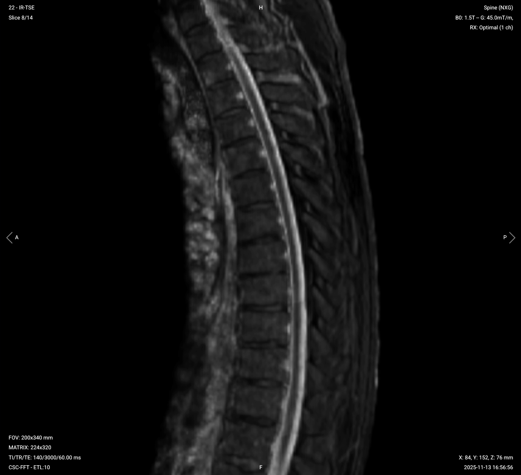
STIR (Short TI Inversion Recovery) suppresses fat signals completely, which makes water-rich tissues stand out even clearer than with normal T2 TSE. This makes STIR ideal for detecting subtle fluid-related conditions like edema, inflammation, and infections, where increased water content would otherwise be obscured by fat.
In the thoracic spine, STIR is particularly useful for identifying bone marrow edema, infections like discitis or abscesses, inflammatory processes, and multiple sclerosis plaques. STIR provides high lesion visibility when water content might not be easily visible on standard T2 sequences.
We acquire STIR in the sagittal view to visualize the entire spine and detect any fluid-related changes across vertebrae or discs.
Fat signal should be completely suppressed, visible as uniform dark signal in the subcutaneous layer and vertebral bodies.
Bone marrow edema, if present, should appear bright and clearly stand out.
Check for inflammatory processes, infections, or multiple sclerosis plaques.
The spinal cord and discs should be clearly visible with good contrast.
Saturation bands should effectively suppress motion artifacts from the heart and lungs.
Final Checks:
Before finishing a thoracic spine MRI, always check these 6 points to ensure diagnostic quality:
Spinal Cord and Discs: The spinal cord must appear continuous and clearly visible on all sagittal and axial images. All 12 thoracic intervertebral discs must be clearly visible with sharp margins.
Coverage and Alignment: Slices must fully cover from at least one cervical vertebra to one lumbar vertebra. Coronal slices must include transverse processes bilaterally. Axial slices should be perpendicular to the spinal cord.
Motion Artifact Suppression: Where a saturation band was prescribed, confirm it cut motion artifact without suppressing spinal signal. Check SAR when bands run across several sequences.
Fat Suppression on STIR: STIR images must show complete fat suppression, with bone marrow edema or inflammation standing out clearly if present.
Image Quality and Artifacts: Images must have strong SNR, crisp detail, and no motion, wrap-around, flow, or susceptibility artifacts. The anterior portion of the spine near the heart should be free from motion blur.
Additional Landmarks: Costovertebral joints should appear symmetric bilaterally on axial images. The diaphragm becoming visible on the lowest slices is expected and signals continued respiratory-motion risk. At the thoracolumbar junction, the conus medullaris should be identified, normally ending around L1–L2 with some normal variation.

.svg)


.png)