How to plan a cardiac MRI viability protocol (part 1)
Written by:
Erik Jacobsson
This step-by-step guide is for MRI students, radiographers and technologists who wish to improve their planning skills and master the cardiac viability MRI protocol.
This guide is Part 1 of a cardiac viability assessment. This first part will focus on:
Cardiac function: The pumping action of the heart
Morphology: The shape, structure, and size of the heart
Key factors in cardiac viability MRIs, including trade-offs.
Patient and scanner setup tips.
Best pulse sequences and planning techniques.
Ways to avoid common artifacts.
What great cardiac viability images should look like.
Key Takeaways
For cardiac viability MRIs, it's generally recommended to prioritize SNR, then resolution, and lastly scan time.
To identify if damaged heart muscle can still heal, we must clearly distinguish between healthy and scarred myocardium.
Strong SNR helps us differentiate bright scar tissues against dark healthy muscle.
To study cardiac morphology and function, we mainly use two types of sequences: 1) Inversion Recovery, and 2) Cine imaging.
Inversion Recovery is used for Black and Bright imaging to examine the heart’s structure and extra-cardiac findings.
Cine imaging creates a live “movie” of the beating heart, which helps us assess its function.
Avoid these 6 common cardiac artifacts.
Artifacts
Solution – How to Avoid It
Motion
Use ECG-gating to synchronize image acquisition with the patient’s cardiac cycle and reduce heart motion.
Breathing
Instruct patients to hold their breath during imaging. Use breath-hold sequences when possible.
ECG mis-triggering
Use real-time cine imaging to minimize the impact of poor ECG signals or arrhythmias.
Flow
Align the phase encoding direction 90° to major vessels to reduce ghosting from blood flow.
Susceptibility
Increase the bandwidth to shorten readout time and reduce distortion from magnetic field variations.
Wrap-around
Use fold-over suppression or phase oversampling to prevent anatomy outside the FOV from overlapping.
Intro to Cardiac Viability MRIs
The heart is a vital organ that pumps blood throughout the body, delivering oxygen and nutrients to tissues. Heart disease remains the leading cause of death worldwide, so accurate heart imaging is key for diagnosis and treatment.
Cardiac viability MRI protocols are critical for evaluating myocardial damagecaused by poor blood flow, often due to heart attacks or coronary artery disease (CAD).
These exams help us determine:
Which parts of the heart muscle are still alive and can recover, and
Which areas are permanently scarred.
This information is crucial for deciding on treatments like revascularization or bypass surgery.
How to Balance the 3 Trade-offs in Cardiac Viability MRIs
In MRI, we always face a trade-off between 3 key metrics:
Scan Time: How fast a pulse sequence can be completed.
Resolution: How much detail the image can display.
SNR: How clear the image is, how much signal relative to noise.
Improving one of these metrics reduces the performance of the others. To decide what trade-offs to make, we must consider the needs of each clinical situation.
For viability MRIs:
The main goal is to clearly distinguish between scarred and healthy heart muscle.
The depth and extent of damage can be just 1–2 mm, so we also need good resolution.
Scan time matters, but we can often afford a bit more time if the patient can cooperate.
Therefore, we typically 1) prioritize SNR, 2) keep high enough resolution to assess scar depth, and 3) optimize for scan time as needed based on patient ability.
This balance ensures we clearly see bright scar tissue against the dark, viable myocardium, which is the whole point of viability imaging.
Note! Prioritizing SNR in cardiac viability MRIs is only a general guideline, NOT a strict rule. If your patient has trouble holding their breath or has arrhythmias, you may need to prioritize scan time instead, using faster, real-time sequences or motion-tolerant techniques. The right balance always depends on the needs of your patient and clinic.
Cardiac Viability/MI Health Conditions – And the MRI Sequences That Reveal Them
The cardiac viability/MI MRI study can help us diagnose a wide range of heart conditions.
In this article, we focus specifically on conditions related to:
Cardiac Function: The pumping action of the heart, and
Morphology: The shape, structure, and size of the heart.
The table below lists some of the most common cardiac conditions related to these two aspects, and what pulse sequences reveal them:
Nulls signal from blood while showing surrounding tissues.
This makes it ideal for fluid collections and fat around the heart.
Excellent for assessing the pericardium and thoracic anatomy.
Captures a real-time “movie” of the heart’s motion through the cardiac cycle.
Enables precise assessment of contraction, ejection fraction, and valve function.
How to Perform a Cardiac Viability MRI: Morphology & Function
This step-by-step guide below will show you how to set up and perform a cardiac viability MRI protocol in practice, focusing specifically on the morphology and function aspects of viability.
We will perform the protocol in 3 parts:
Set up the Patient and MRI Scanner
Plan and Acquire the Protocol Sequences
Review the Images
Part 1: Set up the Patient and MRI Scanner
1. Instruct the Patient to Hold Their Breath
Breath-holding is essential in cardiac MRI to avoid motion artifacts from the diaphragm and chest wall.
When a patient breathes during a scan, the heart and surrounding structures shift, which causes image blurring or ghosting.
To prevent this, we ask the patient to hold their breath at the end of exhale, which is the most stable phase of the breathing cycle.
🗣️ Example – How to Instruct the Patient:
“
“During the scan, I’ll sometimes ask you to breathe in, breathe out, and then hold your breath for about 10–12 seconds. Please stay as still as possible during this time.
We will repeat this practice several times during the scan. But don’t worry. You will have time to catch your breath between each breathhold.”
Let the patient practice once or twice before scanning. Watch their breathing pattern and give coaching if needed.
Cardiac MRI requires many repeated breath-holds, often 15 to 20 times, especially for cine and viability sequences.
If the patient has trouble with breath-holds (e.g., due to age, heart failure, or lung disease), use faster scan techniques or consider free-breathing alternatives with motion correction.
2. Position the Patient and the Coils
Lay the patient feet-first and supine (on their back) with the chest aligned at the scanner’s isocenter.
Using a feet-first position makes the scan feel less claustrophobic for the patient, which reduces the risk of motion artifacts.
Use a dedicated cardiac coil to ensure high-resolution imaging. This coil provides strong signal reception and full coverage of the heart.
✅ Correct Patient Positioning:
3. Place ECG Electrodes and ECG-Gate the Scan
ECG-gating means we use the patient’s electrocardiogram (ECG) to capture each image at the same time point during each heartbeat.
Without gating, images may be acquired during different cardiac phases (points in time during a heartbeat), which leads to motion artifacts caused by heart movement.
To ECG-gate, you need to place three ECG electrodes on the patient’s chest, as shown in the image below:
Traditional placement of ECG electrodes at 1.5 T field strength. Image Credit: Tobias Frauenrath
These electrodes connect to the MRI-compatible ECG box, which tracks the heart’s electrical signal.
For this scan, we rely on a regular RR interval, meaning the patient has a normal sinus rhythm with consistent timing between beats.
If the patient has a heart condition, such as arrhythmia, they may have irregular timing between diastole and systole of the cardiac cycle. This variation can cause missed triggers or skipped beats, which result in artifacts or blurred images.
That’s why it’s essential to check the ECG signal before you begin.
Make sure the ECG trace is strong, clean, and stable while positioning the patient.
Check that the electrode pads are secure and that the cables don’t shift with breathing or movement.
The ECG trace is your guide for the entire scan.
If it’s unstable or disconnects during scanning, image quality may suffer.
4. Check the Scanner’s Hardware Settings
Once the patient is in place, review your scanner’s hardware settings.
In this guide, we will use the following settings:
Scanner Setting
Value
Why This Value
Magnetic field strength
1.5 T
Enables high Signal-to-Noise Ratio, which gives superior image quality. (3 T gives even better signal and resolution, but also brings more artifacts and heat, so most scans use 1.5 T.)
Maximum gradient strength
45 mT/m
Enables faster acquisitions while preserving high image quality.
This hardware setup is widely used in clinical practice. It balances acquisition time, image quality, and patient comfort.
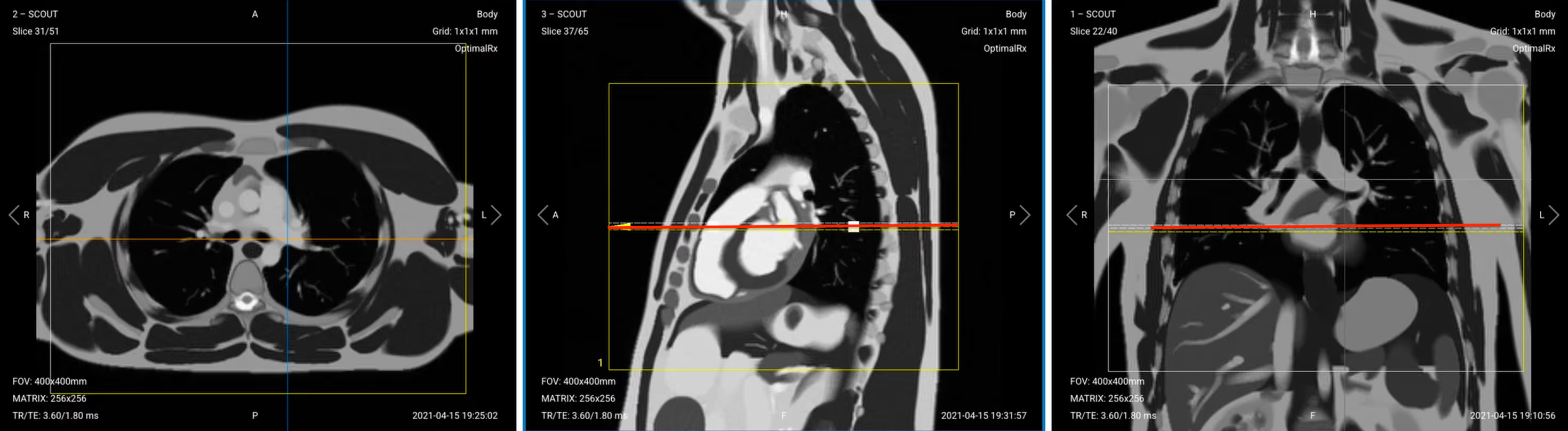
5. Capture the Initial Localizer Images
Before we can perform any MRI protocol, we must always capture initial localizer images of the patient. These images act as a guide for planning the detailed scans we will perform next.
We should always capture localizers in three planes:
Axial
Sagittal
Coronal
Once acquired, upload the initial localizer images into the three viewports.
Then, scroll through each of the image stacks to locate a central slice that clearly shows the anatomy of the heart.
✅ Correct Setup of Localizer Images for Cardiac Viability MRI:
Part 2: Plan and Acquire the Protocol Sequences
When all preparations are ready, we can start planning and acquiring the protocol sequences.
Let's go through the pulse sequences a standard cardiac viability MRI protocol includes, why we perform them, and how to set them up.
This article only focuses on sequences related to cardiac function and morphology.
For cardiac tissue characterization, we will run additional sequences such as perfusion and early/late gadolinium enhancement.
The 8 Sequences of a Standard Cardiac Viability Protocol – Function & Morphology
Black Blood (Extra-Cardiac Anatomy, IR-bSSFP)
Bright Blood (Intra-Cardiac Anatomy, IR-TSE)
Pseudo 2-chamber View (bSSFP)
Pseudo Short-Axis (SAX) View (bSSFP)
4-chamber Cine Imaging (SSFP)
2-chamber Cine Imaging (SSFP)
LVOT / 3-chamber Cine Imaging (SSFP)
SAX Stack Cine Imaging (SSFP)
As you can see from this list above, we mainly use two types of sequences for this study:
Inversion Recoveries: The black and bright sequences both use inversion recovery to examine cardiac structure and detect extra-cardiac findings like effusions.
Cine Imaging: Cines capture the heart's motion like a live movie, which lets us evaluate how the heart muscle moves and identify areas with reduced wall motion.
Both types of sequences use ECG-gating to reduce motion artifacts and thus improve image quality.
In the sections below, we go through how to plan and set up each sequence.
1. Black Blood (Extra-Cardiac Anatomy, IR-bSSFP)
The black blood sequence helps us see extra-cardiac structures, pericardial effusions, and fat infiltration.
✅ Correct Planning:
Planning Instructions:
Add enough slices to cover from the cardiac apex up to the base of the heart, near the mitral valve plane.
Use appropriate slice parameters:
Slice thickness: 6-8 mm
Slice gap: 1-2 mm
Align the slices as follows:
Sagittal localizer: Horizontally through the long axis of the left ventricle, centered at the level of the papillary muscles. Ensure slices extend from apex to base.
Coronal localizer: Perpendicular to the septum, centered through the mid-left ventricle for symmetric short-axis coverage.
Set the fold-over direction (phase encoding) to anterior–posterior to reduce respiratory artifacts.
Parameters for Black Blood (IR-bSSFP):
Parameter
Recommended Values
Why These Values
Echo Time (TE)
1.2–1.8 ms
Very short TE reduces susceptibility and banding artifacts in bSSFP and preserves blood nulling accuracy.
Repetition Time (TR)
4.0–6.0 ms
Very short TR maintains the steady-state signal in bSSFP and supports rapid image acquisition.
Inversion Time (TI)
800–900 ms
TI is timed to null the blood signal based on its T1 value at 1.5 T.
Field-of-View (FOV)
380 × 320 mm
Covers the entire heart and mediastinum with acceptable resolution and minimizing aliasing.
Matrix
192 × 256
Medium matrix size balances spatial resolution, high SNR, and scan speed. Ideal for cardiac anatomy.
Foldover Direction (Phase)
Anterior-to-Posterior (AP)
Reduces motion artifacts from cardiac or respiratory motion, which typically occur in the superior-inferior direction.
Number of Slices
25–40
Ensures coverage from lung apices through the diaphragm to capture the full heart and mediastinum.
Slice Thickness
6–8 mm
Thick enough for full myocardial coverage with good SNR; thinner slices may lose signal in bSSFP.
Slice Gap
1–2 mm
Thin gaps reduce crosstalk and ensure full anatomical coverage without losing detail between slices.
NEX / Averages
1–2
One average keeps scan time short; a second average may improve SNR if motion is an issue.
Turbo Factor / ETL
N/A
Not applicable for bSSFP, which uses single-shot or segmented GRE readout rather than TSE.
Bandwidth
192,000 Hz
High bandwidth shortens TE and reduces susceptibility and flow artifacts common in cardiac imaging.
Flip Angle
50–70°
Optimized to enhance contrast between myocardium and suppressed blood signal while preserving SNR.
Fold-over Suppression
Yes
Prevents aliasing from arms, chest wall, or posterior structures entering the FOV.
2. Bright Blood (Intra-Cardiac Anatomy, IR-TSE)
The bright blood sequence shows intra-cardiac anatomy and chamber dimensions.
✅ Correct Planning:
Planning Instructions:
Copy the slice geometry and planning from the black blood sequence.
Keep the same slice angulation, coverage, and positioning to ensure images of different contrasts can be clearly compared.
Parameters for Bright Blood (Intra-Cardiac Anatomy, IR-TSE):
Parameter
Recommended Values
Why These Values
Echo Time (TE)
1.2–1.8 ms
Very short TE reduces susceptibility and banding artifacts in bSSFP and preserves blood nulling accuracy.
Repetition Time (TR)
4.0–6.0 ms
Very short TR maintains the steady-state signal in bSSFP and supports rapid image acquisition.
Inversion Time (TI)
800–900 ms
TI is timed to null the blood signal based on its T1 value at 1.5 T.
Field-of-View (FOV)
380 × 320 mm
Covers the entire heart and mediastinum with acceptable resolution and minimizing aliasing.
Matrix
192 × 256
Medium matrix size balances spatial resolution, high SNR, and scan speed. Ideal for cardiac anatomy.
Foldover Direction (Phase)
Anterior-to-Posterior (AP)
Reduces motion artifacts from cardiac or respiratory motion, which typically occur in the superior-inferior direction.
Number of Slices
25–40
Ensures coverage from lung apices through the diaphragm to capture the full heart and mediastinum.
Slice Thickness
6–8 mm
Thick enough for full myocardial coverage with good SNR; thinner slices may lose signal in bSSFP.
Slice Gap
1–2 mm
Thin gaps reduce crosstalk and ensure full anatomical coverage without losing detail between slices.
NEX / Averages
1–2
One average keeps scan time short; a second average may improve SNR if motion is an issue.
Turbo Factor / ETL
N/A
Not applicable for bSSFP, which uses single-shot or segmented GRE readout rather than TSE.
Bandwidth
192,000 Hz
High bandwidth shortens TE and reduces susceptibility and flow artifacts common in cardiac imaging.
Flip Angle
50–70°
Optimized to enhance contrast between myocardium and suppressed blood signal while preserving SNR.
Fold-over Suppression
Yes
Prevents aliasing from arms, chest wall, or posterior structures entering the FOV.
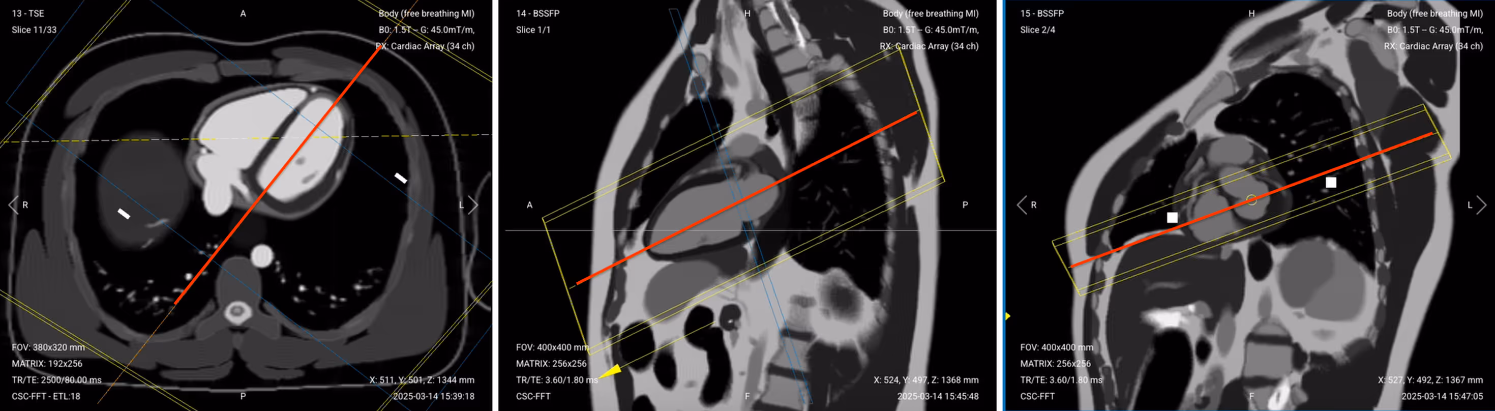
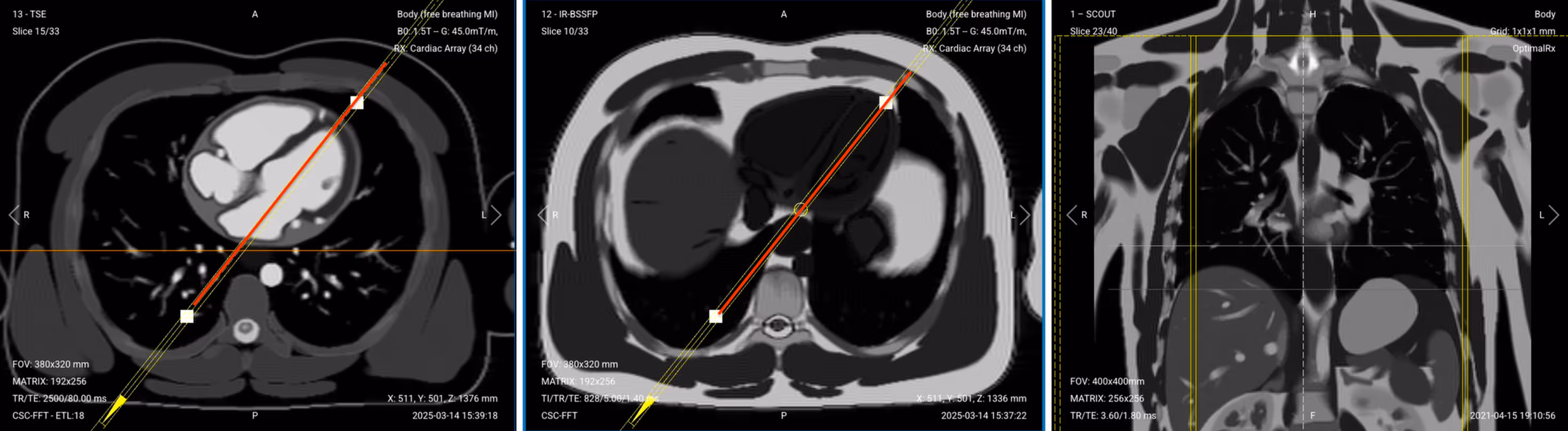
3. Pseudo 2-Chamber View (bSSFP)
This localizer helps us plan the actual diagnostic sequences by capturing a preliminary view of the left atrium and left ventricle.
✅ Correct Planning:
Planning Instructions:
Use the left ventricle, mitral valve, and left atrium as your anatomical references.
Use appropriate slice parameters:
Slice thickness: 6–8 mm
Slice gap: 0–2 mm
Align the slices as follows:
Axial localizer: Rotate the slice so it passes through the apex of the left ventricle and the center of the mitral valve, forming a clean long-axis line through both left-sided chambers.
Coronal localizer: Center the slice over the left heart, avoiding the right-sided chambers.
Set the fold-over direction (phase encoding) to anterior–posterior to minimize respiratory motion artifacts.
Parameters for Pseudo 2-Chamber View (bSSFP):
Parameter
Recommended Values
Why These Values
Echo Time (TE)
1.8 ms
Very short TE minimizes banding artifacts and enhances blood–myocardium contrast in bSSFP.
Repetition Time (TR)
3.6 ms
Very short TR maintains steady-state magnetization for high SNR and bright-blood contrast.
Field-of-View (FOV)
400 × 400 mm
Wide FOV ensures full coverage of the heart in oblique long-axis orientation.
Matrix
256 × 256
High matrix provides sharp in-plane resolution while maintaining fast scan times.
Foldover Direction (Phase)
Anterior-to-Posterior (AP)
Reduces wrap artifacts from lateral chest structures and aligns phase with respiratory motion.
Slice Thickness
6–8 mm
Thick slices provide good coverage and SNR for planning or quick anatomical overview.
Slice Gap
1–2 mm
Small gap prevents overlap and ensures complete coverage for stack planning.
Number of Slices
3–4
Enough slices to cover the pseudo 2-chamber view or enable quick scout imaging.
NEX / Averages
1–2
One average is standard; a second can help if motion or noise is present.
Bandwidth
100,000 Hz
High bandwidth shortens TE and limits susceptibility and off-resonance artifacts.
Flip Angle
50–70°
Balanced to maximize contrast between blood and myocardium in bSSFP imaging.
Fold-over Suppression
Yes
Prevents wrap-around artifacts from arms or posterior chest wall into the image.
✅ Pseudo 2-Chamber View – Correct Image Example:
Things to Look for:
Slice runs from mitral valve to apex
Left atrium and left ventricle are clearly visualized
Bright blood pool with minimal artifact
No wrap or banding artifacts
Chamber walls appear uniform and symmetric
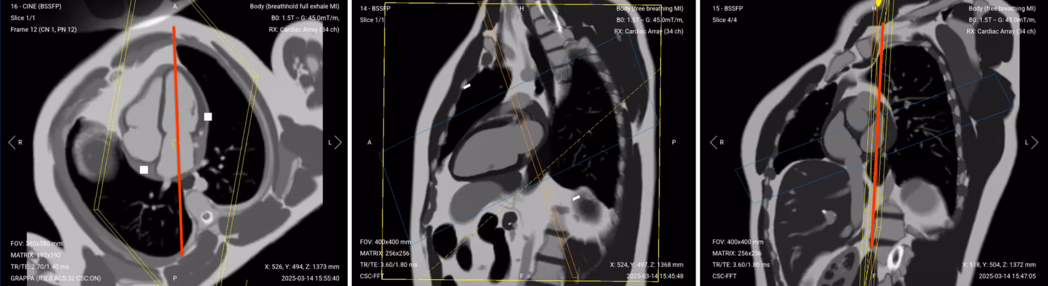
4. Pseudo Short-Axis (SAX) View (bSSFP)
This localizer creates a perpendicular reference to the two-chamber view for planning the cine sequences. This stack helps identify structures to exclude later when refining the final 2-chamber view.
✅ Correct Planning:
Planning Instructions:
Clone the previous pseudo 2-chamber sequence and copy the same slice geometry to use as a starting point.
Use the mitral valve plane, left atrium, and proximal left ventricle as your anatomical references.
Align the slices as follows:
Sagittal pseudo 2-chamber: Rotate the slice so it runs parallel to the mitral valve plane. This defines the pseudo short-axis orientation.
Axial localizer: Confirm the slices remain parallel to the mitral valve plane, perpendicular to the long axis of the heart. Plan to include 3–4 slices:
One slice at the mitral valve
One slice above to include the aorta, pulmonary artery, and left atrial appendage
One or two slices below to include part of the left ventricle
Set the fold-over direction (phase encoding) to right-left to align the phase with the short-axis view, which avoids wrap-around artifacts from anterior/posterior chest.
Parameters for Pseudo Short-Axis (SAX) View (bSSFP):
Parameter
Recommended Values
Why These Values
Echo Time (TE)
1.8 ms
Short TE minimizes banding artifacts and enhances blood–myocardium contrast in bSSFP.
Repetition Time (TR)
3.6 ms
Short TR maintains steady-state magnetization for high SNR and bright-blood contrast.
Field-of-View (FOV)
400 × 400 mm
Wide FOV ensures full heart coverage in oblique short-axis orientation.
Matrix
256 × 256
High matrix provides sharp in-plane resolution while maintaining fast scan times.
Foldover Direction (Phase)
Right-to-Left (RL)
Aligns phase with the short-axis view to avoid wrap-around artifacts from anterior/posterior chest.
Number of Slices
3–4
Captures enough slices to view the heart along the mitral valve plane and surrounding levels.
Slice Thickness
6–8 mm
Thick slices provide good coverage and SNR for quick structural planning.
Slice Gap
1–2 mm
Small gap avoids overlap while ensuring full coverage through the short-axis level.
NEX / Averages
1–2
One average is typical; two improves robustness in motion-prone areas.
Bandwidth
100,000 Hz
High bandwidth shortens TE and reduces off-resonance and susceptibility artifacts.
Flip Angle
50–70°
Balanced to optimize contrast between bright blood and myocardium in bSSFP.
Fold-over Suppression
Yes
Prevents wrap-around artifacts from adjacent anatomy like arms or lateral chest wall.
✅ Pseudo SAX View – Correct Image Example:
Things to Look for:
Image aligned perpendicular to mitral valve plane
Visualizes mitral valve, aortic root, and base of LV
Bright blood with sharp chamber walls
Clear view of left atrial appendage and PA
Minimal motion or off-axis distortion
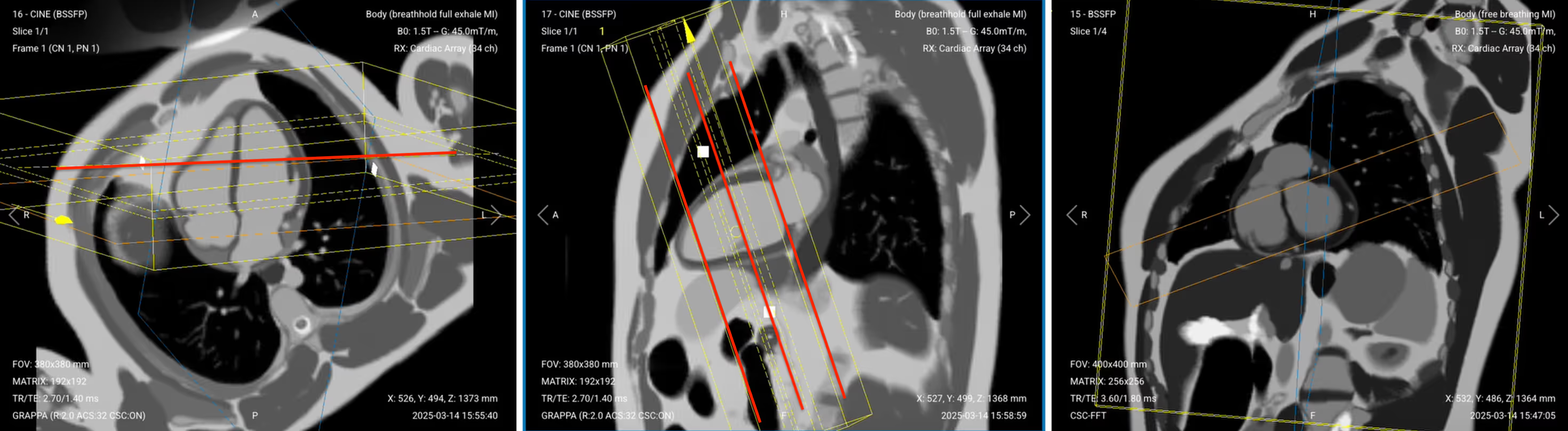
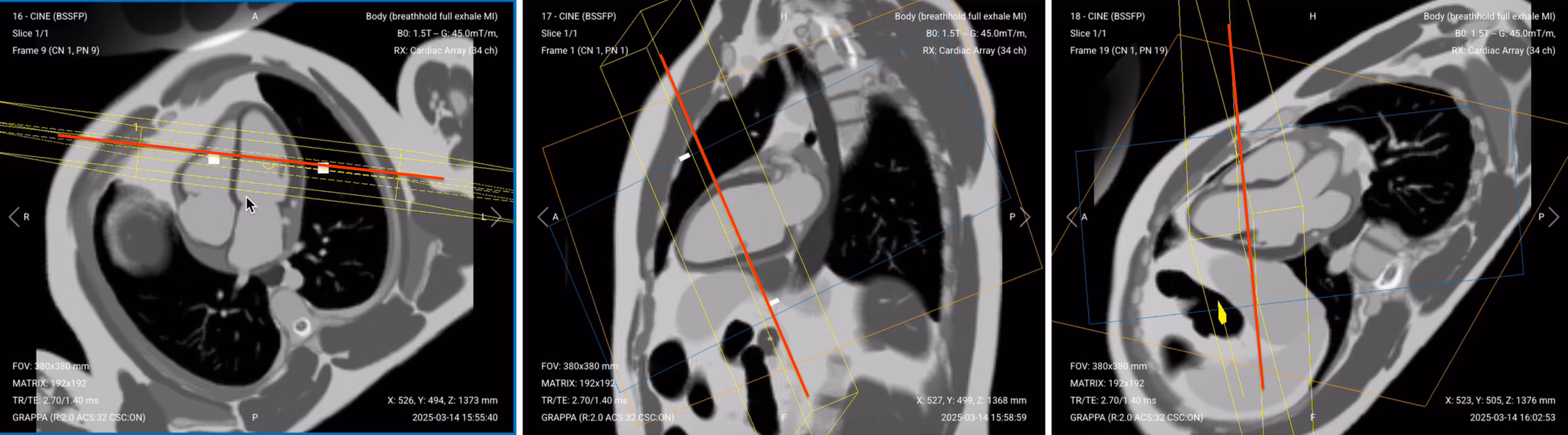
5. 4-Chamber Cine Imaging (SSFP)
This diagnostic view shows all four heart chambers simultaneously, allowing assessment of their relationship.
✅ Correct Planning:
Planning Instructions:
Copy the slice position from the 2-chamber pseudo view as a starting point, then refine it to acquire the full 4-chamber view.
Use the mitral valve, left ventricle apex, and right ventricle apex as key anatomical references.
Align the slices as follows:
Axial localizer: Keep same as in pseudo 2-chamber. Ensure the slice passes through the mitral valve and continues to the apex of the left ventricle, forming a clean long-axis line through both left-sided chambers.
Sagittal 2-chamber pseudo: Adjust the slice to pass through the center of the mitral valve and extend down to the apex of the left ventricle.
Coronal SAX pseudo:
Tilt the slice so it runs below the aortic root and cuts through the right ventricle apex. Angle should intersect the full width of both atria and ventricles.
Scroll through coronal short-axis images to locate the slice where the left ventricular myocardium forms a complete ring (“black donut”). Make sure the 4-chamber cut passes through the center of this donut.
Confirm you see the classic “snowman” appearance: pulmonary artery (head), aorta (body), and left atrium (legs).
Set the fold-over direction (phase encoding) to anterior–posterior to reduce motion and metal artifacts, especially near implanted devices.
For patients with pacemakers or loop recorders, elevate the left arm above the head to reduce artifact interference during cine imaging.
Parameters for 4-Chamber Cine Imaging (SSFP):
Parameter
Recommended Values
Why These Values
Echo Time (TE)
1.4 ms
Very short TE minimizes banding and flow artifacts while preserving sharp contrast between blood and myocardium.
Repetition Time (TR)
2.7 ms
Very short TR maintains steady-state for bSSFP and ensures smooth cine playback with high frame rate.
Field-of-View (FOV)
380 × 380 mm
Sufficient coverage to capture the entire heart, including atria and ventricles.
Matrix
192 × 192
Medium matrix balances spatial resolution and temporal resolution for dynamic imaging.
Foldover Direction (Phase)
Anterior-to-Posterior (AP)
Aligns with chest motion and reduces wrap-around artifacts from lateral structures.
Number of Slices
1
Single slice used for dynamic 4-chamber cine to assess wall motion and valve function.
Slice Thickness
6–8 mm
Thick enough for good SNR and full myocardial wall coverage in motion imaging.
Slice Gap
1–2 mm
Allows spacing between multiple cine planes if needed for stack or reformatting.
NEX / Averages
1–2
One average provides adequate SNR for cine; a second helps if motion artifacts are present.
Bandwidth
120,000 Hz
High bandwidth reduces chemical shift and flow artifacts, allowing for rapid echo spacing and clean image quality.
Flip Angle
50–70°
Optimized to maximize contrast between bright blood and myocardium while maintaining signal stability in SSFP.
Fold-over Suppression
Yes
Prevents aliasing from anterior chest wall or posterior structures entering the image.
Parallel Imaging
GRAPPA
Reduces scan time and echo train length, improving temporal resolution while maintaining image quality.
Acceleration Factor
2–3
Speeds up acquisition by under-sampling in phase direction; factor of 2–3 balances speed and artifact risk.
6. 2-Chamber Cine Imaging (SSFP)
The 2-Chamber view focuses specifically on the left atrium and left ventricle.
✅ Correct Planning:
Planning Instructions:
Clone the previous 4-chamber cine sequence and copy the slice geometry as a starting point.
Keep the same sequence parameters to ensure the different cine views maintain the same contrast so they can be clearly compared.
Use the left atrium, left ventricle, and mitral valve as your anatomical references.
Align the slices as follows:
Axial cine 4-chamber: Adjust the angulation of the field of view to follow the long axis of the left heart, avoiding overlap with the right-sided chambers. Ensure the slice remains centered on the left atrium and ventricle.
Coronal pseudo SAX: Slightly rotate the slice clockwise to avoid the pulmonary artery. Center the slice to run cleanly through the mitral valve and the left ventricular apex.
Parameters for 2-Chamber Cine Imaging (SSFP):
Parameter
Recommended Values
Why These Values
Echo Time (TE)
1.4 ms
Very short TE minimizes banding and flow artifacts while preserving sharp contrast between blood and myocardium.
Repetition Time (TR)
2.7 ms
Very short TR maintains steady-state for bSSFP and ensures smooth cine playback with high frame rate.
Field-of-View (FOV)
380 × 380 mm
Sufficient coverage to capture the entire heart, including atria and ventricles.
Matrix
192 × 192
Medium matrix balances spatial resolution and temporal resolution for dynamic imaging.
Foldover Direction (Phase)
Anterior-to-Posterior (AP)
Aligns with chest motion and reduces wrap-around artifacts from lateral structures.
Number of Slices
1
Single slice used for dynamic 2-chamber cine to assess wall motion and valve function.
Slice Thickness
6–8 mm
Thick enough for good SNR and full myocardial wall coverage in motion imaging.
Slice Gap
1–2 mm
Allows spacing between multiple cine planes if needed for stack or reformatting.
NEX / Averages
1–2
One average provides adequate SNR for cine; a second helps if motion artifacts are present.
Bandwidth
120,000 Hz
High bandwidth reduces chemical shift and flow artifacts, allowing for rapid echo spacing and clean image quality.
Flip Angle
50–70°
Optimized to maximize contrast between bright blood and myocardium while maintaining signal stability in SSFP.
Fold-over Suppression
Yes
Prevents aliasing from anterior chest wall or posterior structures entering the image.
Parallel Imaging
GRAPPA
Reduces scan time and echo train length, improving temporal resolution while maintaining image quality.
Acceleration Factor
2–3
Speeds up acquisition by under-sampling in phase direction; factor of 2–3 balances speed and artifact risk.
7. LVOT / 3-chamber Cine Imaging (SSFP)
The 3-Chamber view shows the left ventricular outflow tract (LVOT), providing important information about the aorta.
✅ Correct Planning:
Planning Instructions:
Clone the previous 2-chamber cine sequence and copy the slice geometry as a starting point.
Use the left atrium, left ventricle, aortic root, and apex as your anatomical references.
Align the slices as follows:
Coronal pseudo SAX: Angle the slice through the center of the aorta and the middle of the left atrium, following the outflow tract. Avoid including the pulmonary artery or right ventricle.
Sagittal 2-chamber cine: Fine-tune the angle so the slice also passes through the apex of the left ventricle and the mitral valve, following the left ventricle’s long axis.
This produces a true LVOT (3-chamber) view, showing the left ventricle, aortic valve, ascending aorta, and left atrium in one plane.
Parameters for LVOT / 3-chamber Cine Imaging (SSFP):
Parameter
Recommended Values
Why These Values
Echo Time (TE)
1.4 ms
Very short TE minimizes banding and flow artifacts while preserving sharp contrast between blood and myocardium.
Repetition Time (TR)
2.7 ms
Very short TR maintains steady-state for bSSFP and ensures smooth cine playback with high frame rate.
Field-of-View (FOV)
380 × 380 mm
Sufficient coverage to capture the entire heart, including atria and ventricles.
Matrix
192 × 192
Medium matrix balances spatial resolution and temporal resolution for dynamic imaging.
Foldover Direction (Phase)
Anterior-to-Posterior (AP)
Aligns with chest motion and reduces wrap-around artifacts from lateral structures.
Number of Slices
1
Single slice used for dynamic 3-chamber cine to assess wall motion and valve function.
Slice Thickness
6–8 mm
Thick enough for good SNR and full myocardial wall coverage in motion imaging.
Slice Gap
1–2 mm
Allows spacing between multiple cine planes if needed for stack or reformatting.
NEX / Averages
1–2
One average provides adequate SNR for cine; a second helps if motion artifacts are present.
Bandwidth
120,000 Hz
High bandwidth reduces chemical shift and flow artifacts, allowing for rapid echo spacing and clean image quality.
Flip Angle
50–70°
Optimized to maximize contrast between bright blood and myocardium while maintaining signal stability in SSFP.
Fold-over Suppression
Yes
Prevents aliasing from anterior chest wall or posterior structures entering the image.
Parallel Imaging
GRAPPA
Reduces scan time and echo train length, improving temporal resolution while maintaining image quality.
Acceleration Factor
2–3
Speeds up acquisition by under-sampling in phase direction; factor of 2–3 balances speed and artifact risk.
8. Short-Axis (SAX) Stack Cine (SSFP)
The Short-Axis stack provides multiple slices from the base to the apex of the heart, allowing for volumetric measurements.
✅ Correct Planning:
Planning Instructions:
Plan the stack using the 2-chamber cine, 4-chamber cine, and pseudo short-axis views.
Use the left ventricle, posterior wall, and interventricular septum as your anatomical references.
Align the slices as follows:
Sagittal 2-chamber cine: Rotate the slice package so it is perpendicular to the posterior wall of the left ventricle. Position the slice stack through the center of the left ventricle and move it slightly downward to optimize coverage.
Axial 4-chamber cine: Align slices perpendicular to the interventricular septum, to follow the heart’s true short axis.
Set the fold-over direction (phase encoding) to foot–head (FH) to reduce wrap and respiratory motion artifacts.
Plan for short breath-hold durations:
Total acquisition time should stay under 1.5 minutes.
Each breath-hold should last 10–12 seconds, matching the time per slice.
Parameters for Short-Axis (SAX) Stack Cine (SSFP):
Parameter
Recommended Values
Why These Values
Echo Time (TE)
1.4 ms
Very short TE minimizes banding and flow artifacts while preserving sharp contrast between blood and myocardium.
Repetition Time (TR)
2.7 ms
Very short TR maintains steady-state for bSSFP and ensures smooth cine playback with high frame rate.
Field-of-View (FOV)
380 × 380 mm
Sufficient coverage to capture the entire heart, including atria and ventricles.
Matrix
192 × 192
Medium matrix balances spatial resolution and temporal resolution for dynamic imaging.
Foldover Direction (Phase)
Foot-to-Head (FH) / Superior-to-Inferior
FH avoids wrap from chest/arms into the heart region. Aligns with natural body length to minimize respiratory artifacts.
Number of Slices
9–12
Depending on patient’s heart size. Use 10 slices for average adult cases.
Slice Thickness
7–8 mm
Thick enough for full heart coverage without large gaps. This improves SNR while keeping resolution acceptable.
Slice Gap
2–3 mm
Set so that Gap + Thickness = 10. For example, if slice thickness is 7 mm, set slice gap to 10 – 7 = 3.
NEX / Averages
1–2
One average provides adequate SNR for cine; a second helps if motion artifacts are present.
Bandwidth
120,000
High bandwidth reduces chemical shift and flow artifacts, allowing for rapid echo spacing and clean image quality.
Flip Angle
50–70°
Optimized to maximize contrast between bright blood and myocardium while maintaining signal stability in SSFP.
Fold-over Suppression
Yes
Prevents aliasing from anterior chest wall or posterior structures entering the image.
Parallel Imaging
GRAPPA
Reduces scan time and echo train length, improving temporal resolution while maintaining image quality.
Acceleration Factor
2–3
Speeds up acquisition by under-sampling in phase direction; factor of 2–3 balances speed and artifact risk.
How to Avoid Artifacts When Planning the Sequences
The table below lists the 6 common cardiac artifacts, and what techniques you can use to avoid them:
Artifacts
Solution – How to Avoid It
Motion
Use ECG-gating to synchronize image acquisition with the patient’s cardiac cycle and reduce heart motion.
Breathing
Instruct patients to hold their breath during imaging. Use breath-hold sequences when possible.
ECG mis-triggering
Use real-time cine imaging to minimize the impact of poor ECG signals or arrhythmias.
Flow
Align the phase encoding direction 90° to major vessels to reduce ghosting from blood flow.
Susceptibility
Increase the bandwidth to shorten readout time and reduce distortion from magnetic field variations.
Wrap-around
Use fold-over suppression or phase oversampling to prevent anatomy outside the FOV from overlapping.
Part 3: Review the Images
Finally, we will review the images to ensure all the anatomical information we need is clear.
In a cardiac viability MRI focused on morphology and function, these structures must be clearly visible:
Left and right ventricles: Including clear borders of the endocardium and epicardium.
Interventricular septum: Check position, motion, and thickness.
Left and right atria: With visible appendages if possible.
Aorta and pulmonary artery: Including outflow tracts and valve motion.
Pericardium: Assess for effusion or thickening.
Diaphragm and posterior lung bases: To check for pleural effusion.
Below, we will go through all the different image contrasts and explain their specific role in imaging the heart.
Black Blood IR-bSSFP – Nulls Blood Signal for Clear Morphological Borders
The black blood uses an inversion recovery to null the signal from flowing blood. This makes moving blood appear black while static tissues like myocardium and fat appear gray/bright. The strong contrast lets us inspect extra-cardiac anatomy, vessel walls, and tissue boundaries.
In cardiac viability imaging, black blood is vital for assessing morphology. It helps identify pericardial thickening, pleural effusion, and fat infiltration. It also confirms proper planning and helps visualize lung bases, diaphragm, and adjacent chest anatomy.
✅ Black Blood IR-TSE – Correct Image Example:
Things to Look for in Black Blood:
Vessels (aorta, vena cava) should be fully black, with no residual signal.
No pleural effusion, which would appear as bright fluid in the lower back part of the lungs.
Liver and biliary ducts may appear bright, as these contain static fluids.
Diaphragm and lung apices should be visible with no distortion.
Clear view of pericardium and adjacent fat or thickening.
Motion artifacts near anterior chest if patient was not breathing consistently.
Bright Blood IR-TSE – Enhances Blood Signal to Show Chamber Structure
This sequence uses an inversion pulse with a TSE readout, which makes flowing blood appear bright while suppressing background tissue. It shows the blood pool, chamber size, and great vessels clearly, with sharp contrast and reduced motion artifacts.
In viability protocols, bright blood is also used to examine morphology, specifically intra-cardiac anatomy, dilation, septal shift, and large effusions.
✅ Bright Blood IR-TSE – Correct Image Example:
Things to Look for in Bright Blood:
Aorta, pulmonary artery, and chambers should appear uniformly bright.
All four chambers must be visible without distortion or wrap artifacts.
Check for clear boundary between blood pool and myocardium.
Look for signs of chamber enlargement or septal shift.
Fluid (pleural or pericardial) may appear brighter than on black blood.
No significant banding artifacts, especially at 3T.
Cine Imaging – Evaluate Cardiac Motion and Chamber Contraction
Cine imaging uses a fast, ECG-gated sequence to capture the heart through multiple cardiac phases. It shows the heart beating like a movie across systole and diastole.
Cine is the gold standard for evaluating global function, such as ejection fraction, wall motion, and ventricular contractility.
In cardiac viability studies, cine images are a must to:
Track ventricular wall thickening and motion.
Visualize valve function and blood flow direction.
Compare end-diastolic and end-systolic phases to calculate EF (Ejection Fraction).
✅ 4-Chamber Cine SSFP of the Heart – Correct Image Example:
Note that the 4-chamber cine image above shows a minor wrapping artifact at its top. But since it doesn’t interfere with the anatomy of the heart, it still meets diagnostic quality.
Things to Look for in 4-Chamber Cine:
All four chambers should be visible and centered.
Mitral and tricuspid valves should open and close fully.
Ventricular walls should contract evenly, especially in the left ventricle.
Blurring or ghosting, which may indicate missed ECG triggering.
Artifacts from metal devices like pacemakers or loop recorders.
Endocardial and epicardial contours are sharp and traceable.
✅ 2-Chamber Cine SSFP of the Heart – Correct Image Example:
Things to Look for in 2-Chamber Cine:
Slice must run through mitral valve and apex.
Left atrial appendage should be visible (shows good alignment).
Avoid including the right ventricle. Keep the view clean.
Myocardium should thicken in systole and relax in diastole.
Crisp motion, without delay or double-exposure.
✅ 3-Chamber (LVOT) Cine SSFP of the Heart – Correct Image Example:
Things to Look for in 3-Chamber (LVOT) Cine:
Slice must pass through left atrium, aortic valve, and apex.
Aortic outflow tract should show clearly, including valve opening.
Smooth transition of blood into the aorta.
Mitral-aortic continuity, no distortion or artifacts.
Basal septal motion and LVOT narrowing.
✅ Short-Axis Stack Cine of the Heart – Correct Image Example:
Things to Look for in Short-Axis Stack Cine:
Stack should cover apex to base without missing slices.
Wall motion must be smooth and symmetric across all levels.
Endocardial and epicardial contours should be easy to trace.
Hypokinetic or akinetic segments that do not contract fully.
Systolic thickening should be visible in healthy myocardium.


.avif)